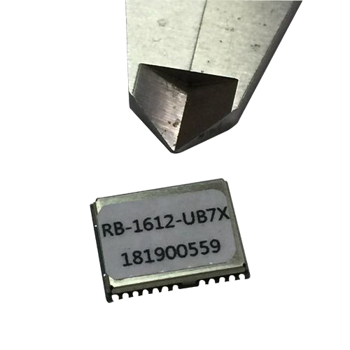
RB1612-UB7X
Product Description
- LBS (Location Based Service)
- PND (Portable Navigation Device)
- Vehicle navigation system
- Mobile phone
Product Feature
- Build on high performance, low-power ublox G7x chip set
- Ultra high Track sensitivity: -165dBm
- Built in high gain LNA
- Perfect compatibility ublox NEO-7Q/M
- Extremely fast TTFF at low signal level
- Low power consumption: Max 35mA@3.3V
- NMEA-0183 compliant protocol or custom protocol
- Operating voltage: 2.8V to 3.6V
- Operating temperature range:-40to85℃
- SMD type with stamp holes
- Small form factor: 16x12.2x2.6mm
- RoHS compliant (Lead-free)
Product Specification
1 Functional description
1.1 Overview
The RB-1612-UB7X series of standalone concurrent GPS modules is built on the exceptional performance of the u-blox 7 GPS (GPS, GLONASS, QZSS and SBAS) engine in the industry proven form factor.The RB-1612-UB7X series provides high sensitivity and minimal acquisition times while maintaining low system power.
The RB-1612-UB7X is optimized for cost sensitive applications, while RB-1612-UB7X provides best performance and easier RF integration. The form factor allows easy migration from previous generations.Sophisticated RF-architecture and interference suppression ensure maximum performance even in GPS-hostile environments.
RB-1612-UB7X modules use ublox 7 GPS chips qualified according to AEC-Q100, are manufactured in ISO/TS 16949 certified sites, and fully tested on a system level. Qualification tests are performed as stipulated in the ISO16750 standard: “Road vehicles – Environmental conditions and testing for electrical and electronic equipment”.
RB-1612-UB7X modules support the u-blox Assist Now Online and Assist Now Offline A-GPS and are OMA SUPL compliant. u-blox’AssistNow Assistance supply aiding information, such as ephemeris, almanac, rough last position and time, reduce the time to first fix significantly and improve the acquisition sensitivity.AssistNow data are with u-blox 7 supporting both GPS constellation for faster acquisition than a GPS-only assistance.
The extended validity of AssistNow Offline data (up to 35 days) and AssistNow Autonomous data (up to 6 days) provide faster acquisition after long off time.
Made of lead-free technology, conforms to the RoHS standard, Single patch, two times more rapid application of SMT scheme.
1.2. Key Features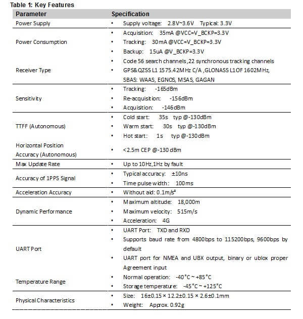
1.2. Block Diagram
The following figure shows a block diagram of RB-1612-UB7X module. It consists of a single chip GPS IC which includes the RF part and Baseband part, a LNA, a SAW filter, a TCXO, a crystal oscillator.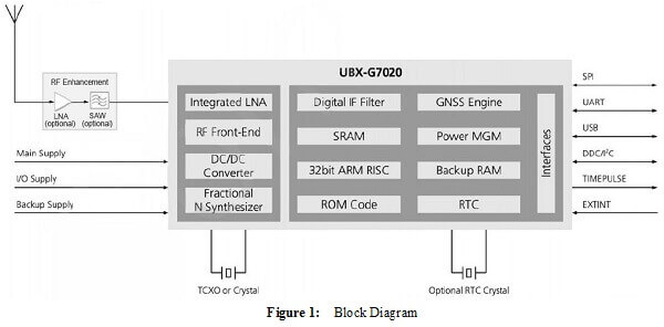
2 Application
The module is equipped with a 24-pin SMT pad that connects to your application platform. Sub-interfaces included in the pad are described in details in the following chapters.
2.1. Pin Assignment
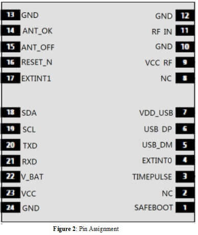
2.2. Pin Definition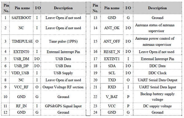
2.3. Power Supply
VCC pin supplies power for BB, RF, I/O, Antenna. The load current of VCC varies according to the VCC level, processor load, the number of tracked satellites and the rate of satellite re-acquisition. Using external active antenna will consume additional 11mA from our module. So it is important to supply sufficient current and make the power clean and stable. VCC supply ripple voltage should meet the requirement: 54mV (RMS) max @f=0…3MHz and 15mV (RMS) max@f >3MHz.
You should choose the LDO without built-in output high-speed discharge function to keep long output voltage drop-down period. The decouple combination of 10uF and 100nF capacitor is recommended nearby VCC pin.
The VBAT pin supplies power for RTC domain. It should be valid when power on the module. The voltage of RTC domain ranges from 1.8V to 3.6V. In order to achieve a better TTFF, RTC domain should be valid all the time. It can supply power for SRAM memory in RTC domain which contains all the necessary GPS information for quick start-up and a small amount of user configuration variables.
- The module's internal power construction is shown as below.
VCC supplies power for PMU, and VBAT supplies power for RTC domain. TIMER signal highlighted in red in the following figure belongs to RTC domain and can be used to control the power switch on/off.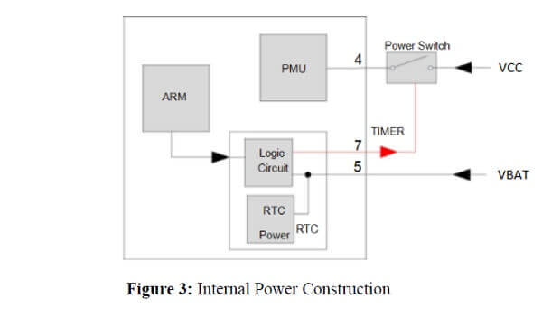
- Power supply solutions for RB-1612-UB7X module are listed as the following.
The simplest power circuit for RB-1612-UB7X module is 3.3V power source connected to VCC pin and VBAT pin of the module directly. In this case, once you powered on the module, the full cold start will be implemented.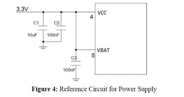
- If your power supply circuit adopts the design mentioned above , RB-1612-UB7X module does not support backup mode.
The other way is feeding VBAT through a backup battery directly. The module will enter into backup mode when power source (3.3V) is cut off. Furthermore,it is necessary to add an external charging circuit.for rechargeable battery. The detailed schematic (mount R2 with 0R to replace Power switch) is shown as there is no charge source when power source (3.3V) is cut off. MS621FE FL11E from Seiko is recommended. The consumption of VBAT is as low as 7uA in backup mode.
The schematic with power supply circuit is shown as below. As power source (3.3V) is always valid and the battery is charged continuously, the capacity of the battery can be small. The detailed schematic for power switch circuit is shown in Figure 5.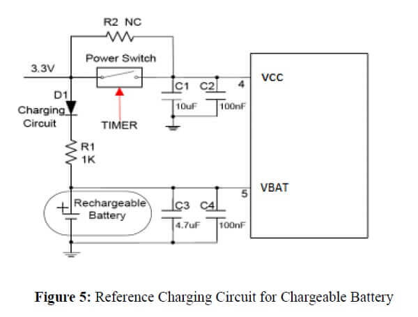
VCC does not supply power for RTC domain in RB-1612-UB7X module, so the VBAT pin must be powered externally. Furthermore, it is strongly recommended to supply power to VBAT through a backup battery, which can ensure RB-1612-UB7X module improves TTFF after next restart. For details about TTFF.
2.4. UART Interface
The module provides one universal asynchronous receiver& transmitter serial port. The module is designed as DCE (Data Communication Equipment), following the traditional DCE-DTE (Data Terminal Equipment) connection. The module and the client (DTE) are connected through the signals shown in the following figure. It supports data baud-rate from 4800bps to 115200bps.
UART port:
UART port: TXD: Send data to the RXD1 signal line of DTE.
RXD: Receive data from the TXD1 signal line of DTE. 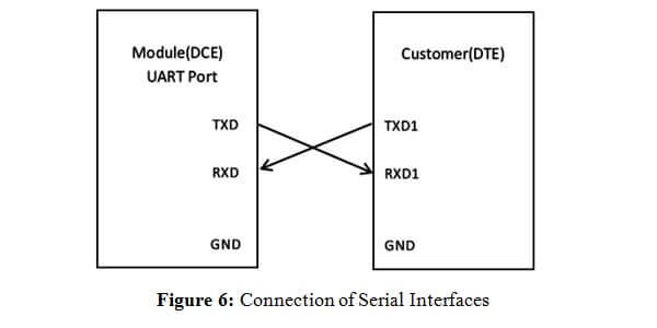
This UART port has the following features:
- UART port can be used for NMEA or UBX Protocol output and proprietary commands input.
- The default output NMEA type setting is RMC, GGA, GSA, GSV, VTG, GLL.
- UART port supports the following data rates:
4800, 9600, 14400, 19200, 38400, 57600, 115200bps.
The default setting is 9600bps, 8 bits, no parity bit, 1 stop bit. - Hardware flow control and synchronous operation are not supported.
The UART port does not support the RS-232 level but only CMOS level. If the module’s UART port is connected to the UART port of a computer, it is necessary to add a level shift circuit between the module and the computer. Please refer to the following figure.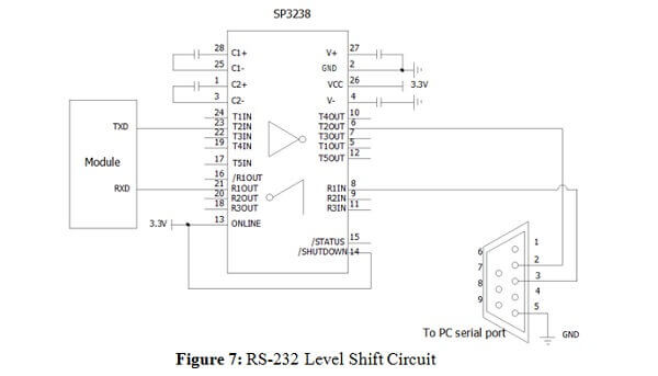
2.5. USB Interface
RB-1612-UB7X modules provide a USB version 2.0 FS (Full Speed, 12Mbit/s) interface as an alternative to the UART. u-blox provides a Microsoft®certified USB driver for Windows XP and Windows Vista operating systems. Windows 7 /8/10 will also be supported following certification.
The module provides a USB general purpose port, Interface contains Module USB circuit power supply VDD_USB, data transmission USB_DM,USB_DP. Supply voltage is 2.8V~3.6V, the maximum can not exceed 3.6V, otherwise it will damage the main chip. Recommended voltage 3.0V. Design circuits such as Figure 8.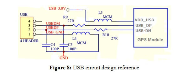
3 Antenna Interfaces
3.1. PCB Design Guide
The RB-1612-UB7X GPS receiver is designed for supporting the active antenna or passive antenna connected with pin RF_IN. The gain of active antenna should be no less than 15dB. The maximum noise figure should be no more than 2.5dB and output impedance is at 50 Ohm.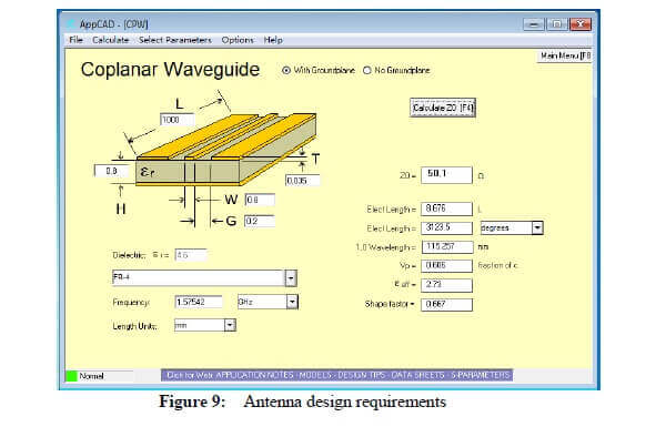
3.2. External Active Antenna
The following figure is a typical reference design with active antenna. In this mode, DC on the VCC_RF pin is powered by VCC and supplies power to the external active antenna.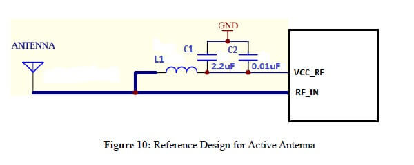
C1, C2, L1 is used for power supply and filtering effect to the external active antenna, RF_IN antenna to a circuit part (BOLD line) for high frequency microstrip line, PCB in the design of this part of the line to calculate the characteristic impedance of the high-frequency line according to the principle of high frequency wiring.
The impedance of RF trace line in main PCB should be controlled as 50 Ohm, and the trace length should be kept as short as possible.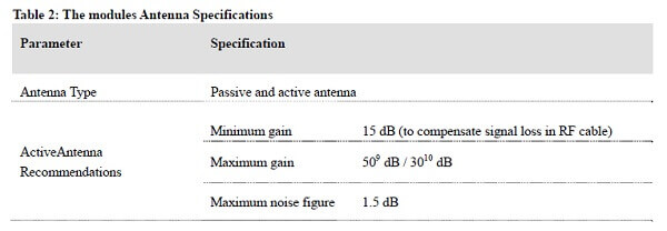
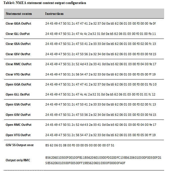
4. Configuration instruction Explain
The module supports the commonly used commands in configuration, The following table describes some of the parameters of the UART port configuration command,baud rate setting: NMEA data refresh rate is set, the NMEA statement output set, positioning mode setting etc.
The Module power up initialization requires 300ms,Please send the sixteen system from CPU via serial port.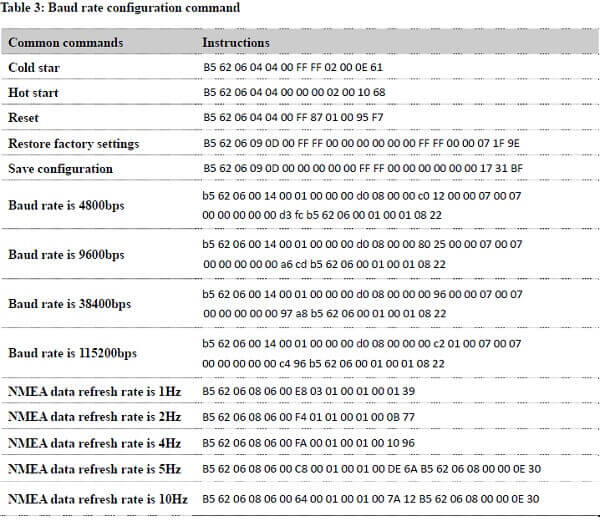
5 Electrical, Reliability and Radio Characteristics
5.1. Absolute Maximum Ratings
Absolute maximum ratings for power supply and vol age on digital pins of the module are listed in the following table.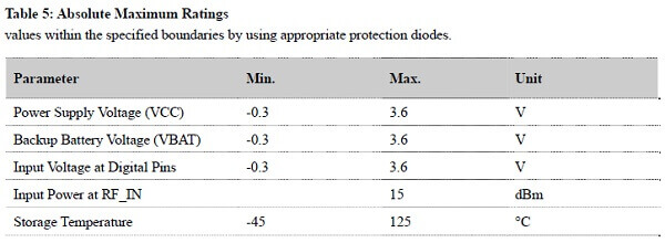
- Stressing the device beyond the “Absolute Maximum Ratings” may cause permanent damage. These are stress ratings only. The product is not protected against over voltage or reversed voltage. If necessary, voltage spikes exceeding the power supply voltage specification, given in table above, must be limited to values within the specified boundaries by using appropriate protection diodes.
5.2. Operating Conditions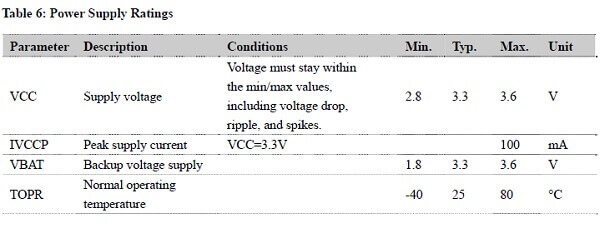
- The figure IVCCP can be used to determine the maximum current capability of power supply.
- Operation beyond the "Operating Conditions" is not recommended and extended exposure beyond the "Operating Conditions" may affect the device’s reliability.
5.3. Current Consumption
The values for current consumption are shown in the following table.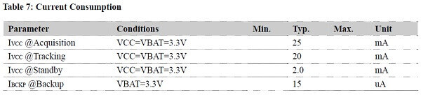
The tracking current is tested in the following conditions:
- In Cold Start, 10 minutes after First Fix.
- In Hot Start, 15 seconds after First Fix.
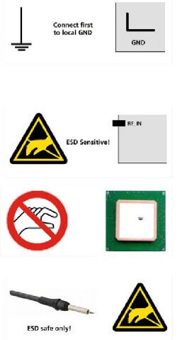
5.4. ESD handling precautions
RB-1612-UB7X series modules are Electrostatic Sensitive Devices (ESD). Observe precautions for handling! Failure to observe these precautions can result in severe damage to the GPS receiver!
GPS receivers are Electrostatic Sensitive Devices (ESD) and require special precautions when handling. Particular care must be exercised when handling patch antennas, due to the risk of electrostatic charges. In addition to standard ESD safety practices, the following measures should be taken into account whenever handling the receiver:
- Unless there is a galvanic coupling between the local GND (i.e. the work table) and the PCB GND, then the first point of contact when handling the PCB must always be between the local GND and PCB GND.
- Before mounting antenna patch,connect ground of the device When handling the RF pin, do not come into contact with any charged capacitors and be careful when contacting materials that can develop charges (e.g. patch antenna ~10pF, coax cable ~50-80pF/m, soldering iron, …)
- To prevent electrostatic discharge through the RF input, do not touch any exposed antenna area. If there is any risk that such exposed antenna area is touched in non ESD protected work area, implement proper ESD protection measures in the design.
- When soldering RF connectors and patch antennas to the receiver’s RF pin, make sure to use an ESD safe soldering iron (tip).
6 Mechanical Dimensions
This chapter describes the mechanical dimensions of the module.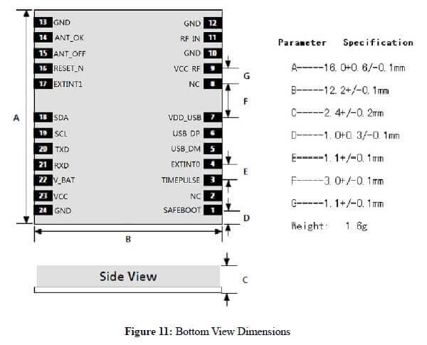
7 Manufacturing, Packaging and Ordering Information
7.1. Assembly and Soldering
RB-1612-UB7X module is intended for SMT assembly and soldering in a Pb-free reflow process on the top side of the PCB. It is suggested that the minimum height of solder paste stencil is 100um to ensure sufficient solder volume. Pad openings of paste mask can be increased to ensure proper soldering and solder wetting over pads. It is suggested that the peak reflow temperature is 235~245ºC (for SnAg3.0Cu0.5 alloy). The absolute maximum reflow temperature is 260ºC. To avoid damage to the module when it is repeatedly heated, it is suggested that the module should be mounted after reflow soldering for the other side of PCB has been completed. Recommended reflow soldering thermal profile is shown below: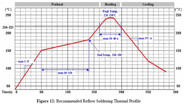
7.2. Moisture Sensitivity
RB-1612-UB7X module is sensitive to moisture. To prevent RB-1612-UB7X from permanent damage during reflow soldering, baking before reflow soldering is required in following cases:
- Humidity indicator card: One or more indicating spots are no longer blue.
- The seal is opened and the module is exposed to excessive humidity.
RB-1612-UB7X should be baked for 192 hours at temperature 40°C+5°C/-0°C and <5% RH in low-temperature containers, or 24 hours at temperature 125°C±5°C in high-temperature containers. Care should be taken that the plastic tape is not heat resistant. RB-1612-UB7X should be taken out from the tape before preheating; otherwise, the tape maybe damaged by high-temperature heating.
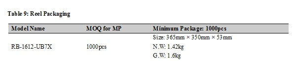
7.3. Tape and Reel Packaging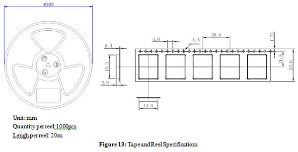
8 Appendix References
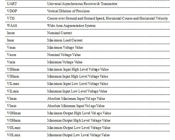
Table 10: Terms and Abbreviations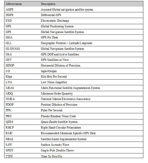
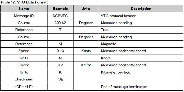
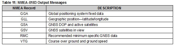
9 NMEA 0183 Protocol
The NMEA protocol is an ASCII-based protocol, Records start with a $ and with carriage return/line feed. GPS specific messages all start with $GPxxx is a three-letter identifier of the message data that follows. NMEA messages have a check sum, which allows detection of corrupted data transfers.
- The RB-1612-UB7X supports the following NMEA-0183 messages: $GPGGA, $GPGLL, $GPGSA, $GPGSV, $GPRMC and $GPVTG.
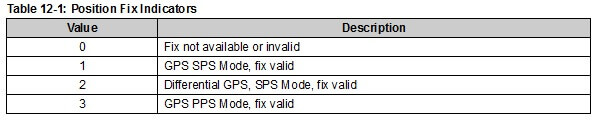
9.1 GGA-Global Positioning System Fixed Data
$GPGGA, 161229.487,3723.24751,N, 12158.34160,W, 1,07,1.0,9.0,M.0000*18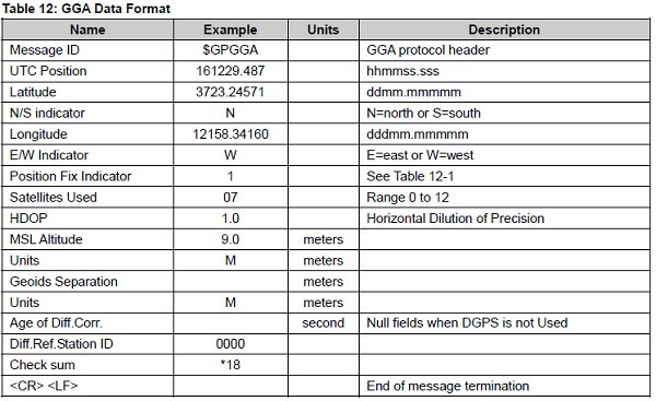
9.2 GLL-Geographic Position – Latitude/Longitude
$GPGLL , 3723.24755, N,12158.34161, W,161229.487, A*2C.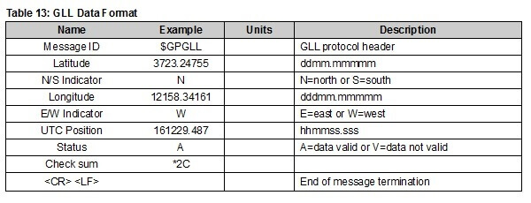
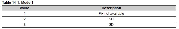
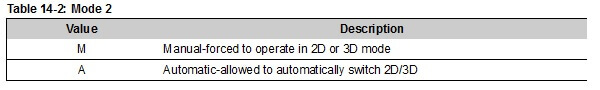
9.3 GSA-GNSS DOP and Active Satellites
$GPGSA , A, 3, 07, 02, 26,27, 09, 04,15, , , , , , 1.8,1.0,1.5*33.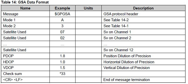
9.4 GSV-GPS Satellites in View
$GPGSV , 2, 1, 07, 07, 79,048, 42, 02, 51,062, 43, 26, 36,256, 42, 27, 27, 138,42*71
$GPGSV, 2, 2, 07, 09, 23,313, 42, 04, 19, 159, 41, 15,12,041, 42*41.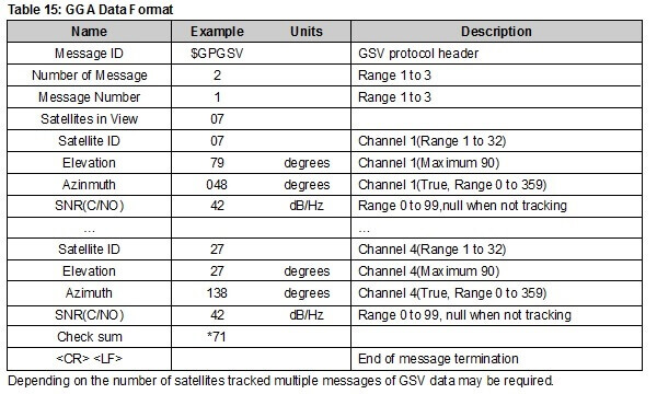
9.5 RMC-Recommended Minimum Specific GNSS Data
$GPRMC, 161229.487, A, 3723.24751, N, 12158.34161, W, 0.13,309.62, 120598,, *10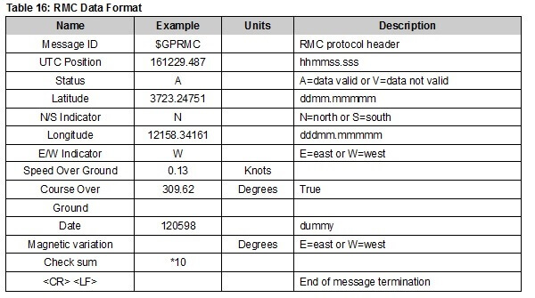
9.5 RMC-Recommended Minimum Specific GNSS Data
$GPVTG, 309.62, T, M, 0.13, N, 0.2, K*6E